

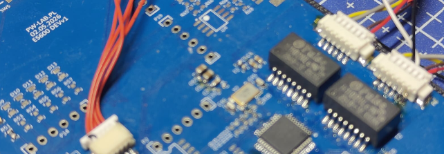
DoIP development board built around the KSZ8863RLL Ethernet switch and STM32
A custom DoIP diagnostic board over 100BASE-T — a KSZ8863RLL Ethernet switch connected to an STM32 via RMII, fully in-house PCB and firmware.
Vehicle diagnostics is increasingly moving from classic CAN to Ethernet-based communication — the DoIP protocol (Diagnostics over Internet Protocol) is now the standard for new ECUs. This board is a custom development platform for working with DoIP at the 100BASE-T physical layer, built around a KSZ8863RLL switch and an STM32 microcontroller.
Why a switch, not just a PHY
The KSZ8863RLL is a three-port Ethernet switch with integrated PHYs, and that choice has a concrete reason here: two external 10/100 Mbps ports handle network traffic, while the third port connects directly to the STM32 over RMII. This setup lets the microcontroller see and filter all DoIP traffic without an extra router or external switch — the switching fabric and control logic live on a single board.
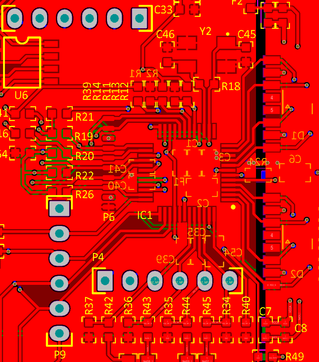
The physical layer is 100BASE-TX, the standard required by most automotive DoIP implementations. The PCB design involved careful differential pair routing, length matching, and separating the PHY’s analog section from the digital domain — standard practice for any Ethernet design, but especially relevant here, since physical-layer mistakes only show up under real network load, not during initial bring-up.
STM32 and RMII
RMII cuts down the pin count compared to classic MII (7 signals instead of over a dozen), which matters on a dense layout, but it requires an externally supplied 50 MHz clock instead of one generated locally by the PHY — here that source is the KSZ8863 itself. The STM32 handles the network stack and DoIP logic: parsing diagnostic frames, managing UDS sessions over Ethernet, and communicating with controllers on the application side.
Scope of work
- Schematic and PCB layout — designed from scratch, with EMC requirements for the Ethernet interface taken into account.
- STM32 firmware — RMII initialization, switch configuration over the management interface, and the DoIP stack.
- Functional testing — verifying the 100BASE-T link, throughput, and communication stability under load.
Result
A compact development board that lets you prototype and test DoIP communication without hooking up expensive, off-the-shelf diagnostic hardware. A good example of a project where hardware-level Ethernet knowledge and automotive diagnostic protocols both need to live in the same team — ideally in the same head.