

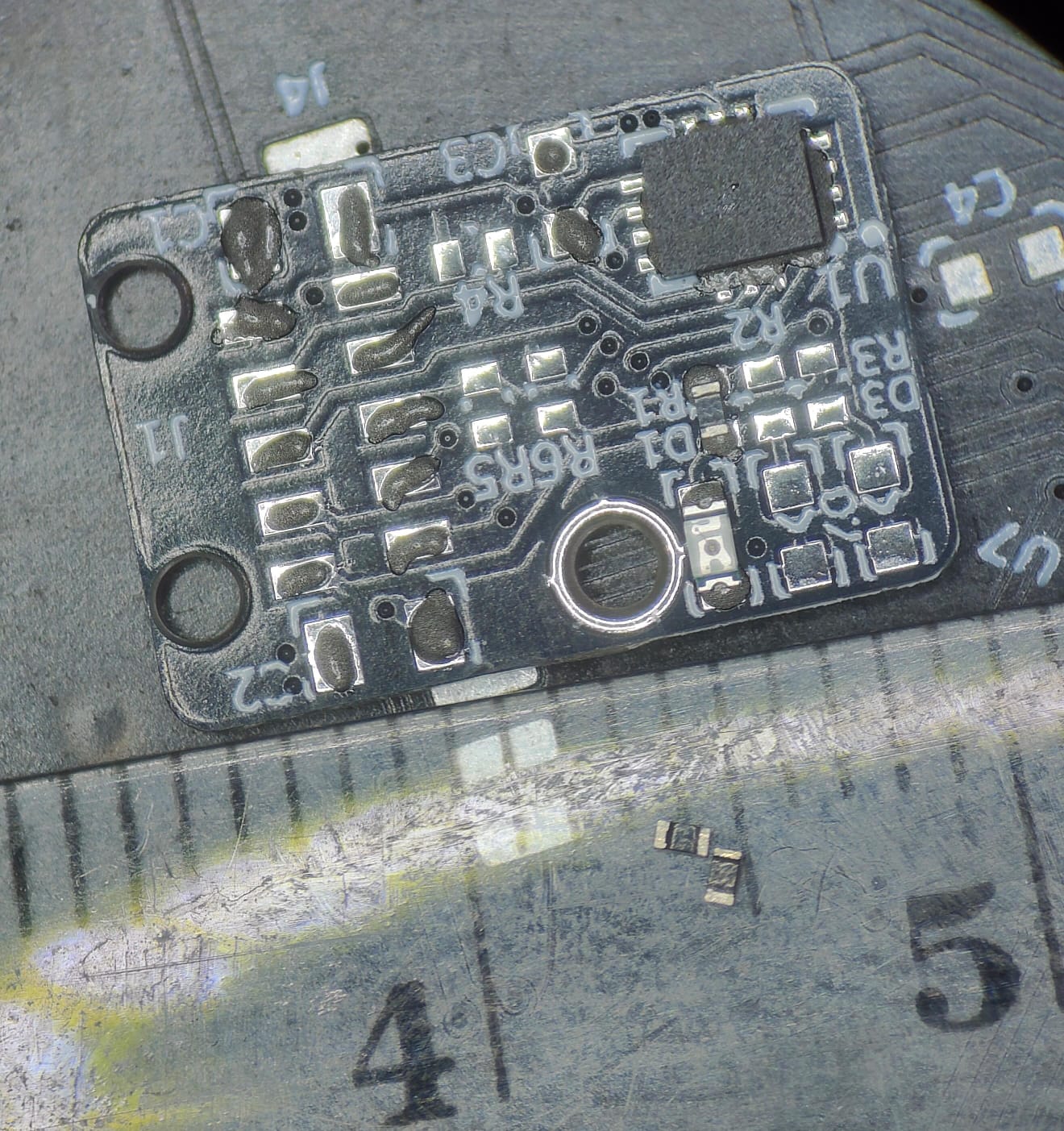
Miniature IMU sensor for gait research — 10×15 mm, SPI, 3D-printed
A 10×15 mm, 0.8 mm-thick IMU sensor with SPI interface and LED status indicators, housed in a 3D-printed enclosure and used in clinical biomechanics research on human gait.
When a biomechanics research team came with their gait-analysis problem, it was immediately clear that off-the-shelf solutions would not work. Commercially available IMU sensors were either too large or too thick — every extra millimetre at the measurement site distorts the natural gait pattern and introduces artefacts into the data. The requirements were straightforward: the sensor had to be invisible to the patient, survive hundreds of gait cycles per day, and fit in the smallest possible enclosure. The result is a PCB measuring 10×15 mm with a thickness of just 0.8 mm, enclosed in a printed housing that fits comfortably in a palm and weighs only a few grams.
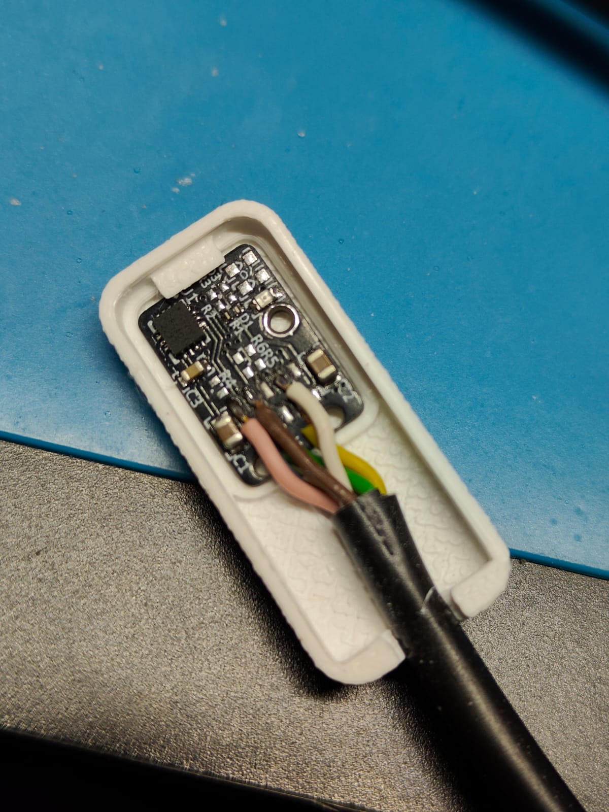
The core of the circuit is a six-axis IMU in an LGA package — accelerometer and gyroscope in a single chip, communicating with the data logger over SPI. The choice of SPI was deliberate: at sampling rates of several hundred Hz and with the need to synchronise multiple sensors simultaneously (the study protocol calls for four measurement points per patient), deterministic transfer timing and the absence of address arbitration like in I²C are a real advantage. The board also carries three LEDs driven directly from GPIO lines: signalling active measurement, data transfer, and error or loss of sync with the logger. Everything is assembled in SMD 0402 technology — decoupling capacitors, SPI pull-up resistors, and LED voltage dividers occupy just a few square millimetres.
The enclosure was printed on an FDM printer in rigid PLA — two parts: a shell holding the PCB and cable, and a flat lid that snaps shut without tools. The SPI cable exits from the rear and connects to the data logger. The design went into use in a longitudinal study involving patients with neurological disorders; early results confirmed that the sensor’s minimal footprint captured subtle push-off asymmetries that the previously used equipment simply could not resolve.